Industrial heat transfer equipment
Custom-engineered shell-and-tube heat exchangers
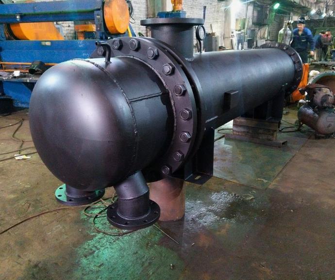
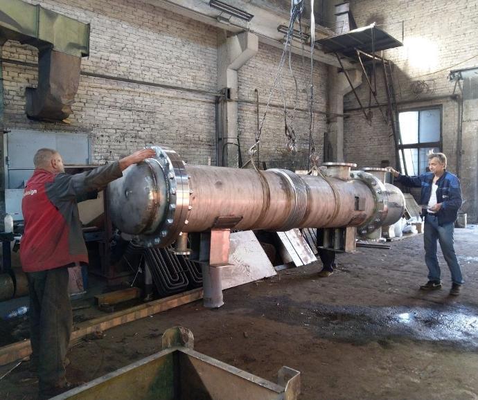
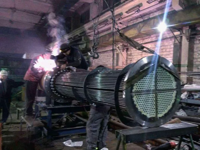
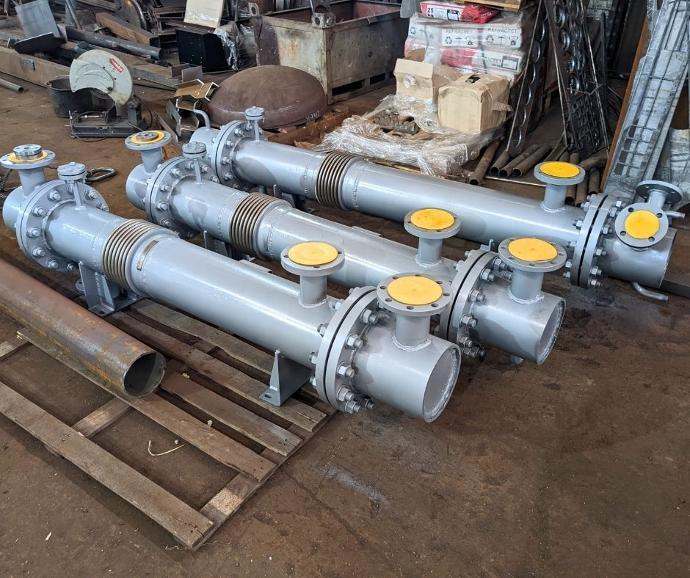
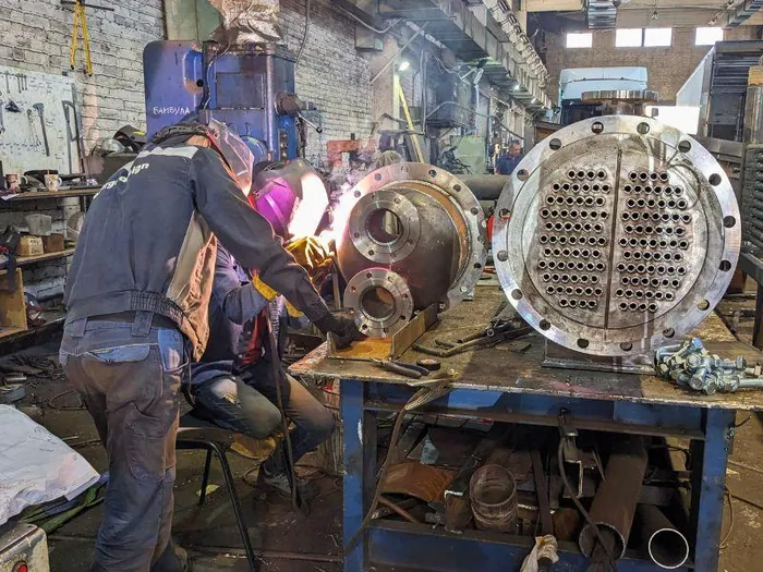
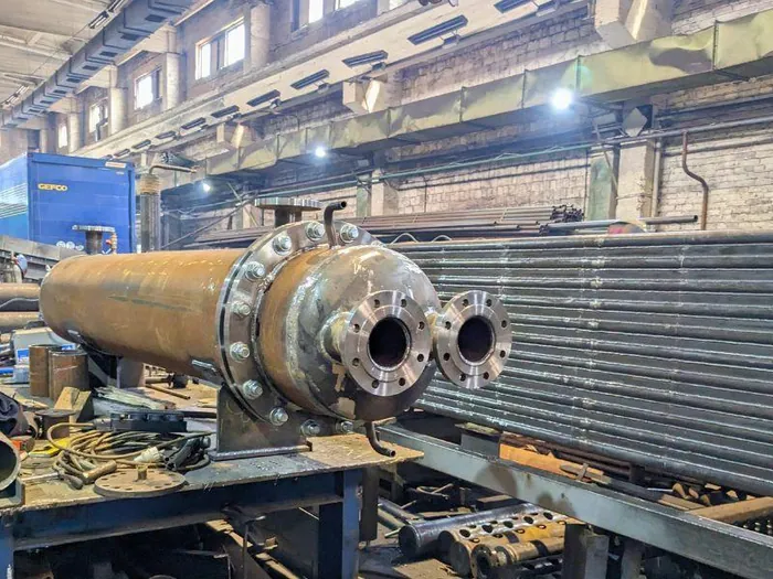
ENERGO.DESIGN designs and manufactures shell-and-tube heat exchangers around the process fluids, thermal duty, operating conditions and site constraints. We review the process data before defining the configuration, materials and equipment layout, then submit the design for approval prior to fabrication.
When to choose a shell-and-tube heat exchanger
Applications and selection criteria
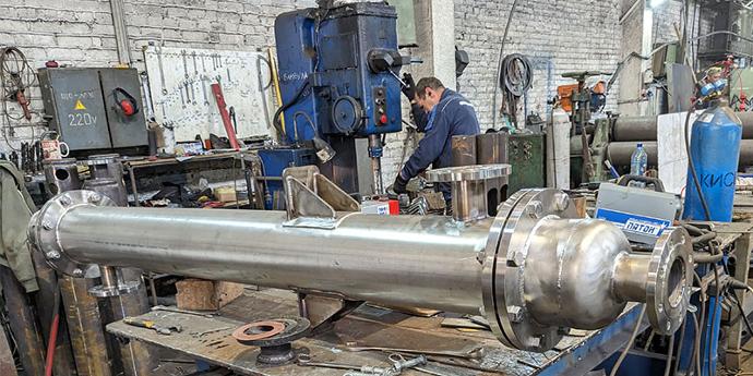
A shell-and-tube design should be considered when thermal duty is not the only deciding factor. Operating pressure, temperature, phase change, allowable pressure drop, differential thermal expansion and access for cleaning may be equally important. The final exchanger configuration is selected after reviewing both process streams and the operating conditions.
The equipment price alone does not reflect the total cost of the solution. At an existing plant, a lower-priced exchanger of another type may require modifications to piping, supports, valves and instrumentation, eliminating the initial saving.
Condensation and evaporation
Heat transfer involving a phase change—vapour condensation or liquid evaporation—with consideration of thermal duty, hydraulic behaviour and the removal of condensate or vapour.
Heating and cooling of liquids
Heat transfer between water, oil and other liquid process circuits where pressure, thermal expansion, fouling or cleaning requirements must be considered.
Shell and tube exchanger: technical solution development
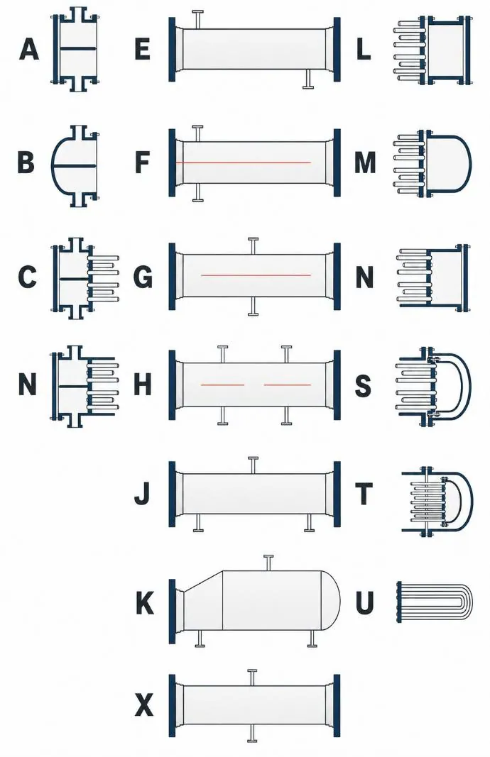
We begin by reviewing the input data and validating the assumptions. We then perform thermal, hydraulic and mechanical calculations, define the configuration and materials, prepare drawings and agree the technical solution before fabrication begins.
Input data
We review fluid properties, operating conditions, material requirements and initial assumptions.
Thermal and hydraulic design
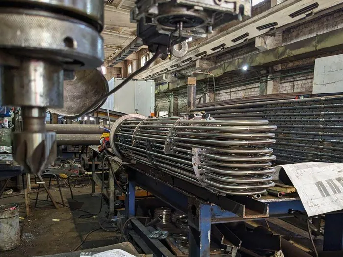
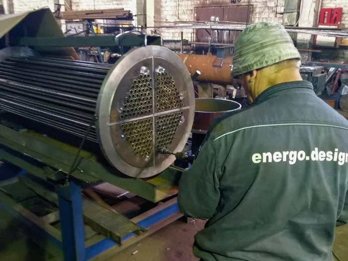
We determine the heat transfer area, tube-bundle arrangement, number of passes, materials and pressure drop.
Mechanical design
We determine the required thicknesses of the shell, tube sheets and other pressure-loaded components.
Drawings and approval
We prepare the drawings and submit the technical solution for customer approval.
Release for fabrication
Following approval, we release the design documentation for fabrication.
Provide process data for heat exchanger sizing
Complete the process parameters available to you. If some data is unknown, leave the corresponding fields blank—we will clarify them while reviewing your enquiry.